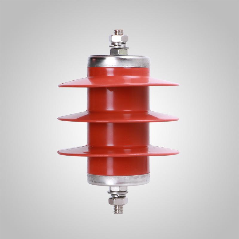
The main role of electrical insulators is to provide mechanical fixation and electrical insulation for electrical equipment and conductors in power transmission and supply lines. Insulators are currently available in three main materials, namely ceramic, tempered glass, and organic composite materials. Insulators have played an important role in the development of the electric power industry.

The porcelain insulator consists of an iron cap, porcelain parts, and steel feet, the iron cap is malleable cast iron, the steel feet are mild steel, and the iron and porcelain parts are cemented together. The iron cap and steel foot of each insulator are insulated. Porcelain insulators are mainly divided into three kinds according to the different directions of use. One is the insulator used in transmission lines, one is the insulator used on electrical equipment in power stations, and the other insulating parts used in other electrically charged bodies also use porcelain insulators. Porcelain insulators mainly play an insulating role while connecting conductors and components in different locations.
It is important to note that insulators are used to provide support and insulation for transmission lines. Therefore, the requirements in terms of mechanical strength or insulation strength are relatively high, and the natural environment in China is relatively complex, so porcelain insulators are mostly used in outdoor and even field environments. Therefore, porcelain insulator products are also required to be able to adapt to complex environmental conditions.
In addition, porcelain insulators are mainly used in high-voltage transmission and supply lines, ultra-high-voltage transmission and supply lines, and the external insulation of electrical equipment in power stations. Therefore, they are required to have high external insulation performance.
In view of the above requirements, the traditional power line insulator testing methods in China are mainly based on the small ball discharge method, infrared thermal camera testing method, and leakage current testing method.
(1) Small ball discharge method: The insulator voltage distribution is analyzed by measuring the distance between the small balls at both ends of the insulator when they are discharged, to determine whether the insulator under test is normal. This method has to adjust the distance of the small ball frequently to analyze the insulator voltage distribution, to determine whether the insulator under test is normal. This method has to adjust the small ball distance frequently, and the misjudgment rate is larger.
(2) Infrared thermal camera detection method: There is a difference between the surface temperature of the bad insulator and a good insulator, which can be shown by a thermal image map through the application of an infrared thermal camera, but the method is difficult to operate when used in the field.
(3) Leakage current detection method: The insulation resistance value of defective insulators will be significantly reduced, and leakage current will be generated. By measuring the size of the leakage current with a current sensor, it is determined whether it is intact.
In summary, these methods have their advantages and disadvantages, but they all have a common defect. That is, they are all qualitative tests, which cannot truly reflect the resistance value of each insulator, and cannot identify insulators that have been leaking but have not yet broken down to a critical damage state.
At present, the rapid development of China’s electric power system, especially the vigorous development of ultra-high voltage and extra-high voltage transmission systems, urgently needs a lightweight, simple, portable, high-altitude operation, fast and accurate insulator detection means of lightweight testing.


